Understanding CT Artifacts: A Comprehensive Guide

Cutting-Edge Advancements in Breast Cancer Screening: What You Need to Know

Introduction
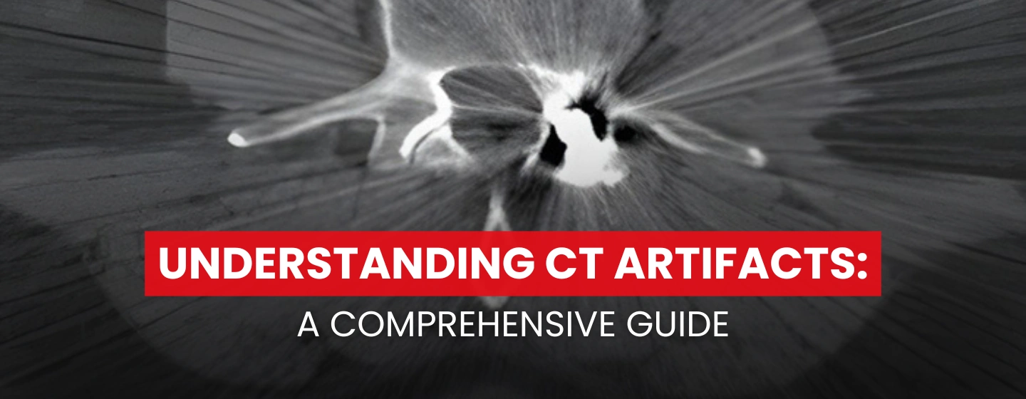
Artifacts are commonly encountered in clinical CT and may obscure or simulate pathology by distorting CT images. At the most basic level, a CT artifact is any discrepancy between the reconstructed values in a CT image and what is expected based on the material density and the sample geometry. They typically manifest themselves as bright or dark streaks or shadows that usually follow some sort of predictable pattern. They can obscure an area of pathology making it impossible for a radiologist to visualize pathology. CT artifacts are common and can occur for several reasons. Knowledge of these artifacts is important because they can mimic pathology (e.g., partial volume artifact). This article is intended to help the reader understand and recognize the distinct types of CT artifacts seen on images.
DEFINITION OF ARTIFACTS
There are numerous distinct types of CT artifacts which include noise, beam sharpening, scatter, motion, helical, cone-beam, and metal artifacts. The term artifact refers to any systematic discrepancy between the CT numbers in the reconstructed image and the true attenuation coefficients of the object. CT artifacts are divided into three categories: Physics-Based Artifacts, Patient-Based Artifacts, and Scanner-Based Artifacts. We will examine all three of these categories.
PHYSICS-BASED ARTIFACTS
When we talk about artifacts arising from the physical processes that are involved in image acquisition, we refer to these as physics-based artifacts. Some examples include beam hardening artifacts, partial volume artifacts, cupping artifacts, photon starvation artifacts, and cone beam artifacts.
- Beam Hardening Effect
Beam hardening is seen with polychromatic X-ray sources. As the X-ray passes through the body, low-energy X-ray photons are attenuated more easily, and the remaining high-energy photons are not attenuated as easily. This is a particular problem with high atomic number materials, such as bone, iodine, or metal. Compared with low atomic number materials, such as water, these high atomic number materials have dramatically increased attenuation at lower energies. At high energies, attenuation is primarily due to Compton scatter.
We have learned that the X-ray beam is composed of a spectrum of energies. When the beam passes through an object, the beam hardens, for example, becomes more high energy dominant. This can result in two types of effects: cupping and streaking, both of which are physics-based CT artifacts.
Beam hardening and scatter are different mechanisms that both produce dark streaks between two high-attenuation objects, such as metal, bone, iodinated contrast, or barium. They can also produce dark streaks along the long axis of a single high-attenuation object.
Scanning at higher kV results in a harder X-ray beam and thus fewer beam-hardening CT artifacts. However, the tradeoff is that there is less tissue contrast at high kV.
Modern scanners perform a simple beam hardening correction that assumes an average amount of beam hardening, given the measured attenuation. However, higher atomic number materials, such as metal, cause a higher-than-average amount of beam hardening and will thus not be fully corrected. This can be addressed using iterative reconstruction.
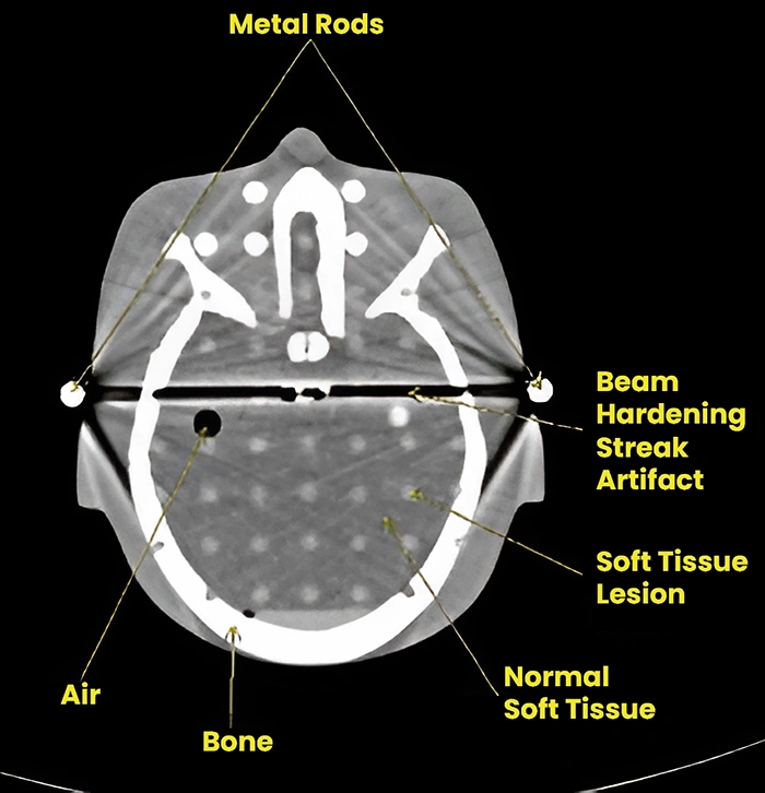
Streaking artifact caused by beam hardening.
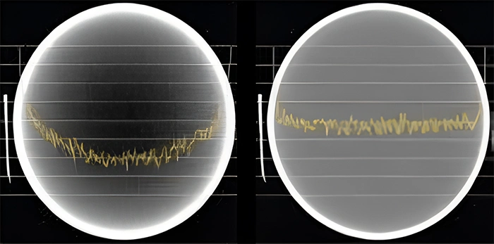
Image with a cupping artifact. & Image without cupping.
- Photon Starving Artifact
A physics-based artifact that results from an insufficient number of photons reaching the detector is known as photon starvation. The result of this causes a statistical variation in photon count which becomes a dominant source of contrast in the image. The resultant image has streaks along high attenuation beam paths such as those intersecting metal objects or those passing through significant volumes of bone.
Photon starvation may be resolved by increasing mAs or using iterative reconstruction techniques.
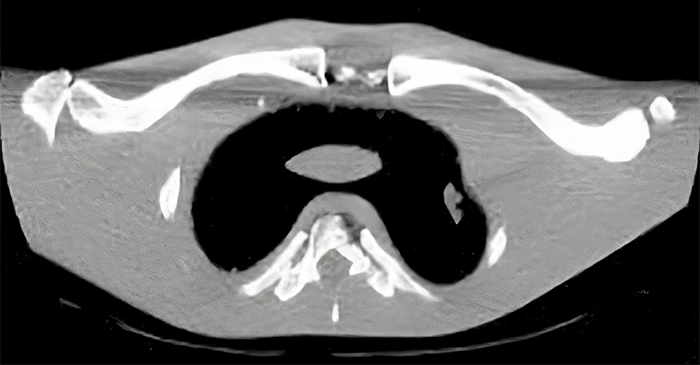
Photon starvation in projections through the clavicle.+
- Cone-Beam Artifact
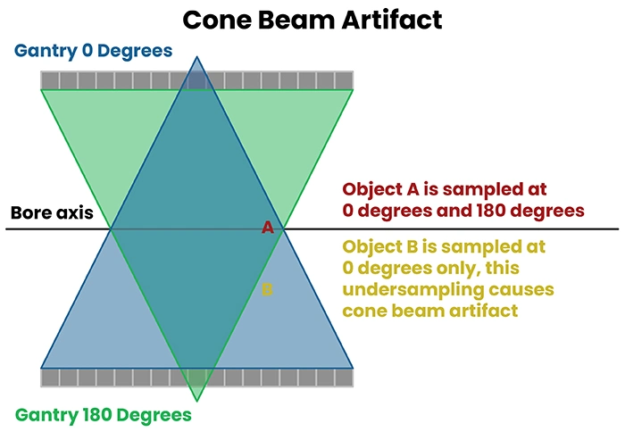
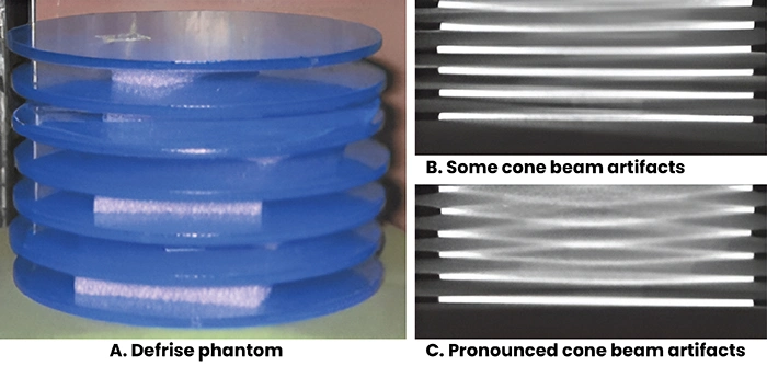
As the number of slices acquired per rotation increases, the beam becomes cone-shaped rather than fan-shaped. Beam divergence of this wide cone can cause under-sampling (collecting data at too few angles) for objects that are far from the central axis of the scanner. This fundamental under-sampling is the cause of cone beam artifact which appears as irregular deformation of the object. Cone beam artifacts can be reduced by decreasing pitch or otherwise increasing sampling.
It should be noted that several online resources list this problem as volume averaging. This is because of a result of a larger volume being collected near the periphery of the detector array. This interpretation is incorrect by noting: 1) all detector elements are commonly the same size; and 2) beam divergence means that, although path length is greater, the cross-sectional area sampled is smaller for objects sampled with the edge row of the detector.
Patient-Based Artifacts
Patient-based artifacts are caused by such factors as patient movement or the presence of metallic materials in or on the patient.
- Noise
Noise can be reduced using iterative reconstruction or by combining data from multiple scans. This enables lower radiation dose and higher resolution scans. Dual- and multi-energy (photon counting) CT can reduce beam hardening and provide better tissue contrast. Methods for reducing noise and out-of-field artifacts may enable ultra-high resolution limited field-of-view imaging of tumors and other structures.
Poisson noise is due to the statistical error of low photon counts and results in random, thin, bright, and dark streaks that appear in the direction of greatest attenuation (see figure below). With increased noise, high-contrast objects, such as bone, may still be visible, but low-contrast soft-tissue boundaries may be obscured.
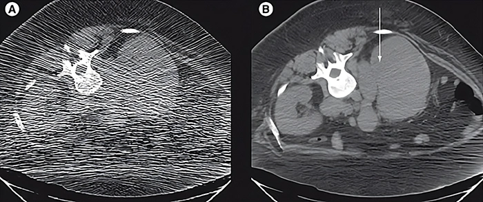
Effect of mA on Poisson noise. (A) Low-dose CT image obtained during a CT-guided biopsy shows extensive Poisson noise (60 mA, 120 kVp, slice thickness 5 mm). (B) Post-biopsy image obtained at 7.3-times higher dose has √7.3 = 2.7-times less noise (440 mA, 120 kVp, slice thickness 5 mm). The images show an enlarged retroperitoneal lymph node (arrow) and infiltration of the right kidney in a patient with Hodgkin’s lymphoma.
Poisson noise can be decreased by increasing the mAs. Modern scanners can perform tube current modulation, selectively increasing the dose when acquiring a projection with high attenuation. They also typically use bowtie filters, which provide a higher dose towards the center of the field of view compared with the periphery. There is a tradeoff between noise and resolution, so noise can also be reduced by increasing the slice thickness, using a softer reconstruction kernel (soft-tissue kernel instead of the bone kernel), or blurring the image. Noise can also be reduced by moving the arms out of the scanned volume for an abdominal CT.
- Motion Artifact
Motion artifact is a patient-based artifact that occurs with voluntary or involuntary patient movement during image acquisition. Patient motion during a scan can result in misregistration of the ray data. This usually appears as blurring, directional shading, or streaking in the reconstructed image. Motion artifacts may be reduced by improved patient immobilization, patient coaching, or increased scan speed.
If this movement is voluntary, patients may require immobilization or sedation to prevent this from occurring. When this motion is involuntary, such as respiration or cardiac motion, it may cause artifacts that mimic pathology in the surrounding structures. The artifact caused by involuntary can be reduced by using a fast-scanning technique.
Motion (patient, cardiac, respiratory, or bowel) causes blurring and double images, as well as long-range streaks. The streaks occur between high-contrast edges and the X-ray tube position when the motion occurs. Faster scanners reduce motion artifacts because the patient has less time to move during the acquisition. This can be carried out with faster gantry rotation or more X-ray sources.
More detector rows allow a greater volume to be imaged in a single gantry rotation, this increases the distance between step-off artifacts from motion on coronal or sagittal reformats. Rigid body motion artifacts (a problem with head CT, as seen in this head image) can be reduced using special reconstruction techniques. Respiratory motion in cone-beam CT with slow gantry rotation can be estimated and corrected, thus reducing artifacts. Techniques, such as cardiac gating, may be used for examinations that concern the mediastinum.
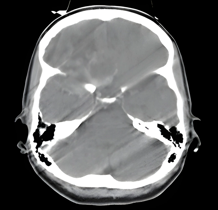
Motion artifact in a head CT. Motion causes blurring and double images, as well as long-range streaks.
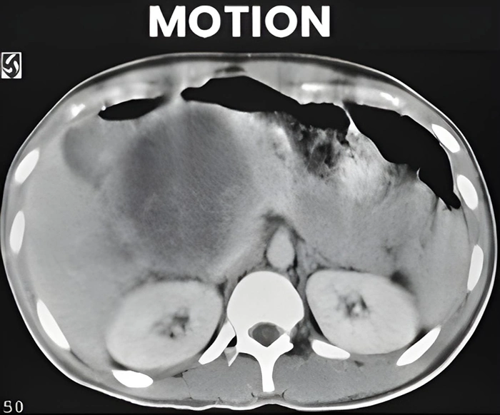
Motion as seen in the abdomen
- Metal Artifact
Metal streak artifacts are extremely common, seen in 21% of scans in one series. They are caused by multiple mechanisms, some of which are related to the metal itself and some of which are related to the metal edges. The metal itself causes beam hardening, scatter effects, and Poisson noise, which are discussed above. Beam hardening and scatter result in dark streaks between a metal with surrounding bright streaks.
Metal artifacts are particularly pronounced with high atomic number metals, such as iron or platinum, and less pronounced with low atomic number metals, such as titanium. In some cases (i.e., dental fillings on head CT scan), patient positioning or gantry tilt can angle the metal outside of the axial slices of interest.
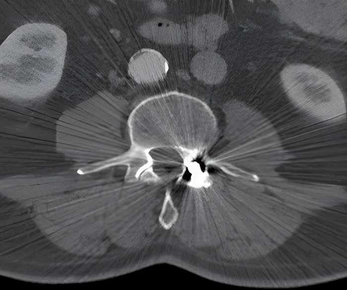
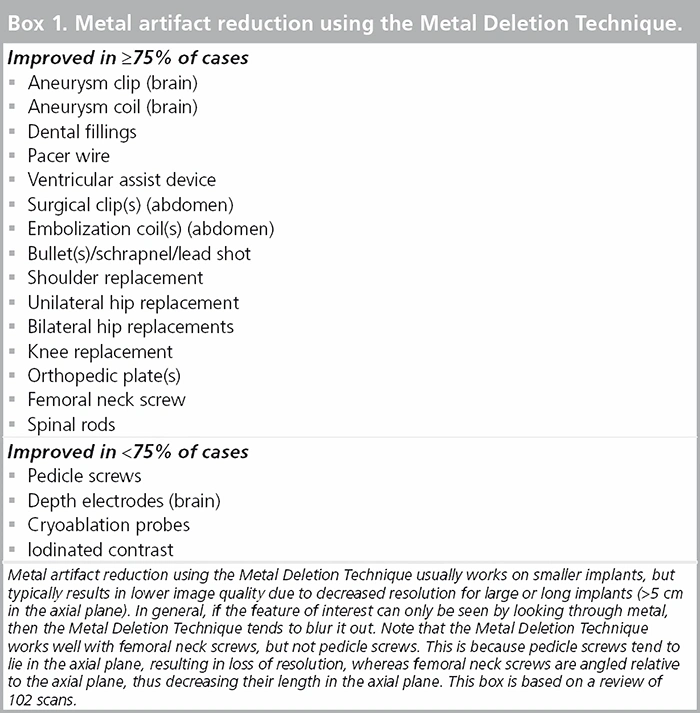
Several techniques have been proposed for metal artifact reduction. Metal artifacts can also be reduced using iterative reconstruction, resulting in a more accurate diagnosis. One such method is the Metal Deletion Technique.
Metal Deletion Technique (MDT)
While several techniques have been proposed for metal artifact reduction, an iterative method called the Metal Deletion Technique (MDT), which is based on the principle that projection data involving or near metal is less accurate, owing to the mechanisms discussed above has been developed and seems to help. This means that instead of trying to look through the metal to see soft tissue, we look around the metal. It also means that any features that can only be seen by looking through metal will be lost, and structures that are within a few millimeters of metal are blurred out.
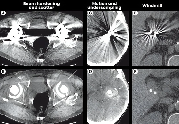
Metal Deletion Technique reduces different types of metal artifacts and can reveal new findings as seen in these images. (A) The dark streak between hip replacements is mostly due to beam hardening and scatter. (B) The Metal Deletion Technique image more clearly shows a fluid collection adjacent to the left hip replacement. (C) Sharp, thin alternating streaks surrounding an aneurysm coil are mostly due to motion and under-sampling. (D) Metal Deletion Technique image reveals hemorrhage around the coil. (E) Smoothly undulating streaks around cholecystectomy clips are due to windmill artifacts. (F) Metal Deletion Technique reduces this artifact.
Scanner-Based Artifacts
Scanner-based artifacts result from imperfections in the scanner function. Helical and multisection technique artifacts are produced by the image reconstruction process. Design features incorporated into modern CT scanners minimize some of the types of artifacts, and many can be partially corrected by the scanner software. However, careful patient positioning and optimum selection of scanning parameters are the most crucial factors in avoiding CT artifacts.
- Partial Volume Averaging
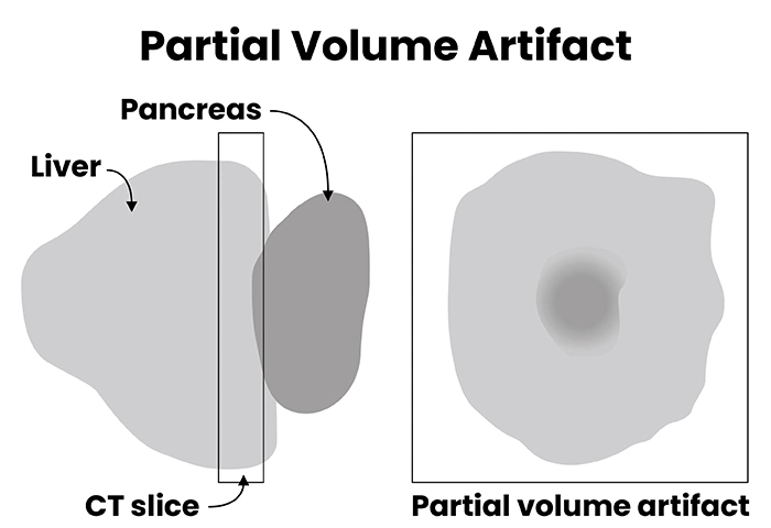
Partial volume artifacts occur when tissues of widely different absorption are encompassed on the same CT voxel producing a beam attenuation proportional to the average value of these tissues.
Partial volume artifact is the averaging of CT number over the volume of the voxel. For example, a voxel that samples a bone (CT number = 800HU) and lung (CT number = -800) would display a CT number of 0 which is representative of water.
Partial volume averaging is particularly problematic in CT angiography (e.g., misdiagnosis of an apparent contrast filling defect caused by the artifact as PE). Therefore, the use of thin section reconstructions (1-1.5 mm) is recommended where the impact of this artifact is negligible. The latest generation of CT scanners with an associated reduction in the volume of a voxel has reduced the occurrence of this artifact.
- Ring Artifacts
Ring artifacts are a CT phenomenon that occurs due to the miscalibration or failure of one or more detector elements in a CT scanner. Less often, it can be caused by insufficient radiation dose or contrast material contamination of the detector cover. They occur close to the isocenter of the scan and are usually visible on multiple slices at the same location. They are a frequent problem in cranial CT. This can sometimes simulate pathology (see figure below).
Recalibration of the scanner will usually rectify the artifact. Occasionally detector elements need replacing, which can be costly. The referring clinician should be notified that the concerning ring shadows are artifactual.

Ring artifact. (A) Pelvic CT showing severe ring artifact. (B) Head CT with subtle ring artifact simulating a pons lesion (arrow). (C) Changing the window/level settings shows the circular reconstruction region, which is centered at the center of rotation. The pons pseudo lesion (marked with a small circle) is exactly at the center of the circular reconstruction region and thus consistent with a ring artifact. Follow-up with an MRI showed a normal pons.
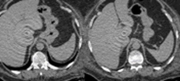
Ring artifacts in the abdomen.
- Cone Beam Artifacts
In multidetector row CT, the projection planes which are defined by the x-ray source and the detector row are not exactly parallel to the axial plane. This is all except for the center detector row. In the simplest 2D FBP reconstruction, the projection planes for each detector row are assigned to the closest axial plane based on where they intersect the center of rotation. If there is a high-contrast edge in the z-direction between the axial plane and the projection plane, this creates streaks, as well as stair-step artifacts (see figure below).
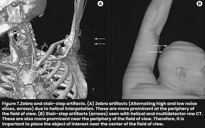
These effects are worse with an increased number of detector rows. These artifacts can be reduced with Adaptive Multiple Plane Reconstruction (AMPR), which uses tilted planes for reconstruction. Cone-beam reconstructions, which reconstruct the entire 3D volume at the same time using the correct multidetector row geometry also reduce this artifact, but they are much slower. Clinical flat panel detector CT scanners use cone-beam reconstruction.
PROJECTION/VIEW (ALIASING or UNDER SAMPLING)
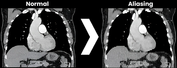
Aliasing artifact, otherwise known as undersampling, in CT, refers to an error in the accuracy proponent of analog to digital converter (ADC) during image digitization. Image digitization has three distinct steps: scanning, sampling, and quantization.

Summary
Since its introduction in 1972, CT has seen several generations of improvements, including multidetector row helical CT, improved spatial and temporal resolution, dual-energy CT, and iterative reconstruction. Most artifacts from the early days of CT are now substantially reduced, but some artifacts remain, and modern technologies have introduced new, incompletely characterized artifacts.
Remarkable progress has been made in the past few years on iterative techniques for reducing metal artifacts and noise. These techniques not only improve image quality, but can also reduce the radiation dose, improve spatial resolution, and improve diagnosis. However, with iterative reconstruction, noise, and image quality are decoupled, which will require new measures of image quality as well as subjective evaluation.
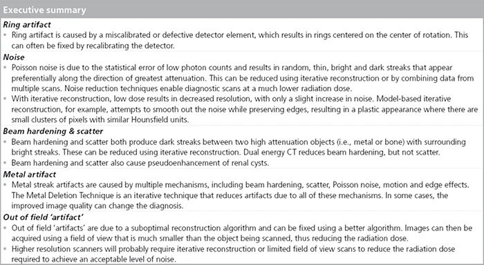
The chart above synthesizes a few of the discussed artifacts that can be found in CT images. I hope you have enjoyed this article and have taken away some additional knowledge on artifacts in CT.
References
- 4nsi.com
- radiopaedia.org
- Barrett JF, Keat N. Artifacts in CT: recognition and avoidance. Radiographics. 2004;24 (6): 1679-91. dx.doi.org
- openaccessjournals.com
- openaccessjournals.com
- openaccessjournals.com
- openaccessjournals.com
- openaccessjournals.com
- Liu X, Primak AN, Krier JD, Yu L, Lerman LO, McCollough CH. Renal perfusion and hemodynamics. accurate in vivo determination at CT with a 10-fold decrease in radiation dose and HYPR noise reduction.Radiology 253, 98–105 (2009).
- Supanich M, Tao Y, Nett B et al. Radiation dose reduction in time-resolved CT angiography using highly constrained back projection reconstruction. Phys. Med. Biol. 54, 4575–4593 (2009).
- oncologymedicalphysics.com
- openaccessjournals.com
- Jerrold T. Bushberg, John M. Boone. The Essential Physics of Medical Imaging. (2011) ISBN: 9780781780575
- doi.org
- Bushberg JT, Seibert JA, Jr. EML et-al. The Essential Physics of Medical Imaging. LWW. ISBN:0781780578.
- openaccessjournals.com
Disclaimer: The information provided on this website is intended to provide useful information to radiologic technologists. This information should not replace information provided by state, federal, or professional regulatory and authoritative bodies in the radiological technology industry. While Medical Professionals strives to always provide up-to-date and accurate information, laws, regulations, statutes, rules, and requirements may vary from one state to another and may change. Use of this information is entirely voluntary, and users should always refer to official regulatory bodies before acting on information. Users assume the entire risk as to the results of using the information provided, and in no event shall Medical Professionals be held liable for any direct, consequential, incidental or indirect damages suffered in the course of using the information provided. Medical Professionals hereby disclaims any responsibility for the consequences of any action(s) taken by any user as a result of using the information provided. Users hereby agree not to take action against, or seek to hold, or hold liable, Medical Professionals for the user’s use of the information provided.
