The Role of a Medical Physicist in a Radiotherapy Center

The Role of a Medical Physicist in a Radiotherapy Center


Introduction
Medical physicists apply their knowledge of physics and technical methods to all parts of medicine to conduct research, establish or refine theories, and solve problems related to human disease diagnosis, treatment, and rehabilitation. A medical physicist brings a unique perspective to the clinical team in a radiation oncology program to provide the best service to the patients. The physicist collaborates with the radiation oncologist, radiotherapy technologist, and others to ensure that all parts of a treatment prescription are delivered accurately. In radiation oncology, physicists are responsible for the commissioning, planning, and verification of dosimetry and calibration in radiation therapy, which will be further discussed in this article.
1. Commissioning
First, the medical physicist has to plan for resource allocation with radiation oncologists, administrators, and technologists, including equipment usage, selection and replacement, commissioning requirements, and continuing review of the program policies and procedures. In addition, he is responsible for the maintenance of all instrumentation required for calibration of the LINAC, measurement of radiation, and dose calculation before starting the treatment of any patient.
1.1 Beam profile and percentage depth dose (PDD)
The medical physicist has essential work to perform the commissioning procedure and acceptance tests of the different beams and energies according to the LINAC characteristics. First, the beam profile measurement is mandatory to visualize the shape of the beam at different angles. Then a percentage depth dose of each energy is required to be sure that the dose is distributed in the water phantom at different beam dimensions with a flattening filter and without a flattening filter for different energies. Figure 1 shows the experimental setup for PDD measurements. Figure 2 presents the graphs of the 6MV and 6FFF energies, compares the measured and calculated values, and visualizes the absolute difference according to the beam dimensions.
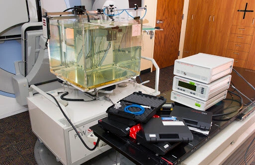
Fig 1: Water phantom used for commissioning.
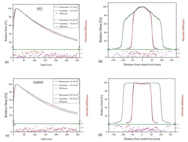
Fig 2: Pdd and beam profile of 6MV and 6FFF energies
1.2. CT to ED conversion curve
Some treatment planning systems (TPS) use the Electron density for fluence and dose calculation. The medical physicist has an essential role in measuring by scanning the phantom where there are different materials. Using the mean Hounsfield Units (HU) given by the TPS, the medical physicist can make the conversion curve from HU to electron density (ED). Specific HU values can be used to find the corresponding ED from the standard manual. This calibration shall be done once according to the CT scan onsite, when the CT is changed the calibration shall be repeated according to the new scanner. Figure 3 shows the specific phantom used to determine the conversion value from HU to ED.
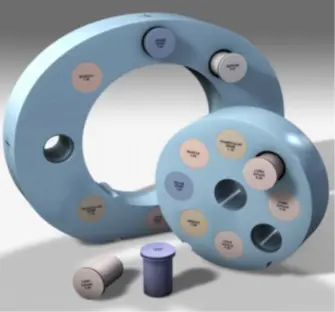
Fig 3: Phantom for HU calculation
Although the appropriate range for use is 0-3 g/cm3, in some cases the patient’s CT may generate RED values as high as 15 g/cm3. The medical physicist must be cognizant of the dose calculation inaccuracies associated with the use of values out of the appropriate range. Some materials can be used to calculate the conversion values with increased ED around 15g/cm3. Figure 4 shows the CT to ED curve used to convert from HU to ED for different imported study sets, and Figure 5 shows the values used by the system for dose calculation of a Head and Neck case.
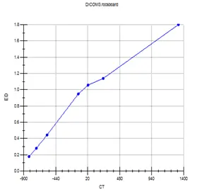
Fig 4: CT to ED curve
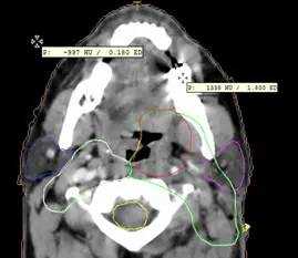
Fig 5: ED in different mediums
1.3 Couch insertion and measurement
During the irradiation of a patient some beams emerge from the couch, which means that there is a percentage of the photons attenuated by the couch, and change the dose distribution at the skin of the patient and in the region of interest near the tumor. For this reason, the couch shall be inserted into calculation in the TPS to reduce as much as possible the difference between the calculated dose and the received dose by the patient during the treatment. Figure 6 shows the couch inserted into the calculation, the voxel inside this contour will be included in the calculation.
The medical physicist has to make couch measurements to apply the specific electron densities according to the couch used in the Clinique, he has to force the value of the carbon fiber and foam core (to 0.4 and 0.02 respectively for Elekta equipment) and then choose the coronal plane and export from the TPS. The next step is to Import this dose plane and the measured data into the QA Software, the two planes will be compared to be sure that they are close values. This couch should be saved in the library and will be used in each new patient.
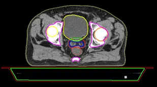
Fig6 : Couch insertion
Figure 7 shows the volumes and the electron densities of the couch inserted for a head and neck case, the system will calculate the dose absorbed by the couch and gives the real value received by the patient.

Fig7 : Couch ED values
1.4. Post modeling
Post modeling is the process of verifying the MLC geometry parameter values of a TPS pMC model against LINAC measurements done with local QA phantom. It is recommended to perform post-modeling analysis for all pMC models that will be used with IMRT or VMAT treatments. Post-modeling will help optimize the QA agreement for clinical IMRT and VMAT treatments in the clinic. The medical physicist must know the steps to perform a post-modeling test using the following devices:
- IMRT QA Detector (‘QA device’)
- Predefined phantom or water equivalent slabs
- ExpressQA plan in TPS for your MLC model
Post-modeling serves to optimize MLC Geometry and re-calculate the same plan after each iteration to see how it is affecting the model and repeat this procedure until optimal agreement. For this reason, a template called Express QA can be used and different measurements can be applied multiple times during this procedure. From this point, the medical physicist will focus on the TPS optimization. The shape of segments of the Express QA plan will be always the same to keep consistency, as a result, the plan and measurements will not be affected, and the impact is only on the calculated dose. Figure 8 shows the different steps of a post-modeling test.
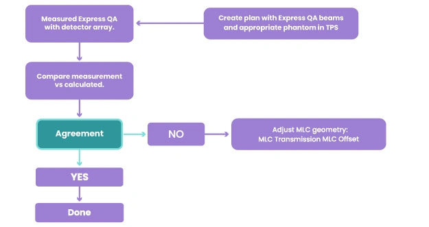
Fig 8: Post modeling steps
1. Planning
- CT (computed tomography) scan.
- MRI (magnetic resonance imaging).
- PET (positron emission tomography) scan.
- PET-CT scan
When the CT scan is performed, the study set will be exported from the scanner to the TPS. The medical physicist has to import the study set, compare different images, and make the fusion between CT, Scanner, and MRI or CT and Pet CT to help the oncologists contour the PTV and all organs at risk. In addition, a 4D contouring technique can be used in case of a moving tumor inside the patient. Then, a computer program analyzes the 3D image and designs radiation beams that conform to the shape of the tumor. During this step, the medical physicist has to insert the couch and create the beams using the best orientation of the gantry, couch, and collimator. In addition, he has to precise the prescription, the isocenters, setup and reference points, dose reference point, improve the plan quality to remove the hotspots from the dose distribution, improve the plan to cover the PTV as much as possible when reducing the dose in the organ at risk.
The planning can be a 3D forward plan or intensity-modulated radiation therapy (IMRT) according to the shape, the complexity, and the location of a tumor. The Oncologist and the medical physicist can discuss together to decide which delivery type is the best according to the patient’s case.
2.1 3D conformal
In 3D conformal radiation therapy, the segments will be created manually to match the shape of the tumor. In the past, radiation beams only matched the height and width of the tumor exposing healthy tissue to radiation. Advances in imaging technology have made it possible to locate and treat the tumor more precisely. Conformal radiation therapy uses the targeting information to create the segments, use wedges if needed, and focus precisely on the tumor while avoiding the healthy surrounding tissue. This exact targeting makes it possible to use higher levels of radiation in treatment. More radiation is more effective in shrinking and destroying tumors. Figure 9 and Figure 10 show the dose distribution of 3D conformal plans for prostate and breast cases respectively.
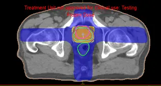
Fig 9: Dose distribution of a prostate 3D plan
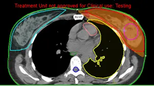
Fig 10: Dose distribution of a breast 3D plan
2.2 Intensity Modulated Radiation Therapy (IMRT)
IMRT is a sort of sophisticated radiation therapy that is used to treat cancer and non-cancerous tumors. IMRT manipulates photon and proton beams of radiation to conform to the shape of a tumor using modern technologies. During IMRT, the medical physicist has to use different cost functions to control the dose distribution in the PTV, organ risk, and patient. The segments will be automatically created to be conformed to the PTV with automated weight given to each function, as a result, the dose will be perfectly conformed to the PTV with a very low dose to the organ at risk. Figure 11 and Figure 12 show the dose distribution for a Neck and prostate case respectively.
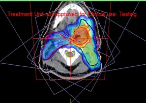
Fig 11: Dose distribution of a IMRT neck plan
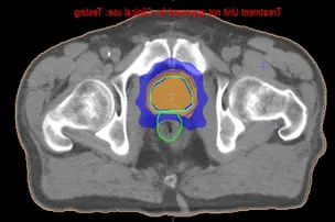
Fig 12: Dose distribution of an IMRT prostate case
Plan evaluation
3.1 DVH Statistics
DVH statistics is a table that presents the maximum dose, the minimum dose, the mean dose, and the hot reference dose and volume receiving this dose.
The medical physicist can evaluate the dose received by the organs at risk, the PTV, and the patient. The aim is to be sure that the parallel organs and serial organs are protected and that the PTV is completely covered by the required dose. Figure 13 shows the statistics of all the organs of the patient, the medical physicist can easily evaluate the plan by checking these values and comparing them to the tolerances of the organs given by international standards.
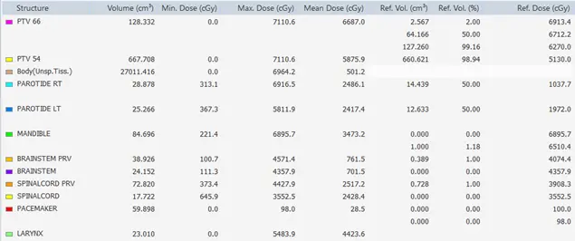
Fig 13: Statistics of different organs
3.2 Dose-to-Volume Histogram
The dose distribution data can be converted to Dose to volume histogram, so the medical physicist can evaluate the shape of the DVH, and the volume received by the reference dose of the contoured organs. Figure 14 shows the DVH of all the structures of simultaneously Integrated PTVs. The medical physicist can easily evaluate the dose received by a volume of any needed structure.
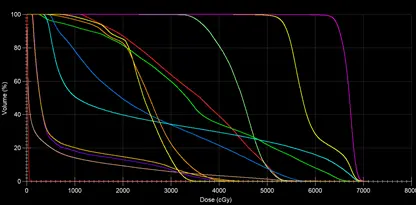
Fig 14 : DVH of the contoured structures
3.3 Dosimetric Criteria
Dosimetric criteria can be introduced to facilitate the evaluation of a plan. The list of all the tolerances of the different organs can be presented and if the condition is verified the system will indicate different signs. Figure 6 shows the dosimetric criteria of the different organs with the tolerances of RTOG standards, when the condition is verified, the system indicates the green sign on the right. Figure 15 shows the dosimetric criteria requested by the oncologist, the tolerances are all respected for each organ, and the green icon near each condition facilitates the evaluation of the plan.
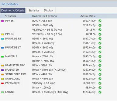
Fig 15: Dosimetric criteria of a Neck case
3.4 Dose Substruction
The medical physicist can compare two plans by substructing the dose in each voxel of the two-dose distributions. As a result, the medical physicist can see the voxels having less or more doses between the 2 plans. This technique is useful for choosing the more adequate plan according to the tolerances required by the oncologist.
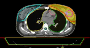
Fig 16: Dose distribution in the PTV of Plan 1
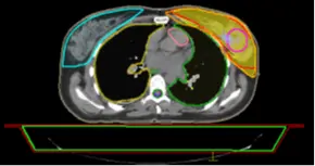
Fig 17: Dose distribution in the PTV of Plan 2
The medical physicist can have difficulties evaluating 2 plans, so he can load the 2 plans together to check the dose distribution and then make the substruction of these 2 plans. In this example, Figure 18 shows the substruction Plan 1 – Plan 2.
The substruction of the 2 plans gives spatial information about the 2 plans. In Figure 18 the dose is higher in Plan 1 by 326.8 cGy in the region of red color, this difference will be less in the region of green color and then Plan 2 has a higher dose because the value is negative, this value will decrease to -326.8 in the region of blue color.
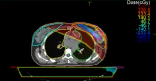
Fig 18: Substruction Plan 1 – Plan 2
4. Plan approval
The approval of a treatment plan is an important stage in the radiotherapy treatment process. The medical physicist has to know that it’s critical to agree on what we mean by plan quality and to understand the characteristics it’s based on. After achieving all the evaluation steps mentioned previously, the medical physicist can approve the plan and the plan will be ready to export to a record and verify system. The medical physicist can add any comments to transmit any additional information before exporting. Figure 19 shows the window where the physicist can approve the plan and export it automatically to the record and verify system.

Fig 19: Plan approval
5. Plan Quality assurance
Plan Quality Assurance is an essential step for IMRT plans. During this step, the medical physicist has to calculate the dose from the TPS and export it to a QA software to compare with the measured values using a specific phantom. Because of the complicated beam intensity modulation, each IMRT field generally contains a large number of small irregular off-axis fields, resulting in more conformal isodose distributions for each IMRT plan than for conventional treatment plans. As a result, these characteristics impose a new set of QA requirements for IMRT planning and delivery that are more stringent.
The QA plan should be done and calculated to ensure that the TPS calculation is similar to the measured dose distribution in the phantom, this study will ensure that the patient is receiving the same dose during the treatment. This QA plan will be done before starting the treatment of any new patient. The justification for this approach is that piecewise uncertainties in both the planning and delivery phases are responsible for the overall accuracy of IMRT delivery. Figure 20 shows the calculated and measured plans, we have an acceptable gamma index and high pass rate, the plan can be delivered to the patient.
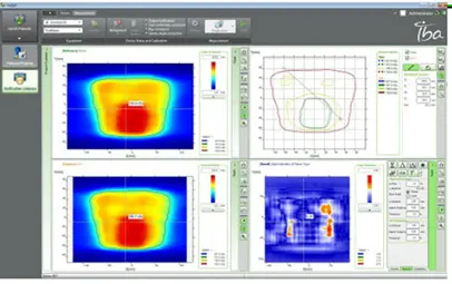
Fig 20: Plan quality assurance
6. Positioning of the patient, coordination with therapist
As we know, the medical physicist’s goal is to deliver a high dosage of radiation to a specified volume in a succession of defined fractions. High repeatability of the patient’s posture is required to ensure the efficacy of the therapy and the patient’s safety.
The first step of positioning is to determine the scan and setup references. The medical physicist has to determine the shift between the scan references and the beam isocenter. In some TPS the system will calculate the difference automatically and send them to the record and verify system.
After the shifts are sent to the record and verify system, the therapists are responsible of the positioning of the patient according to the medical physicist’s conditions. Figure 21 shows the scan and setup references and the shifts are automatically calculated by the system and exported to the record and verify system.
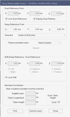
Fig 21: Scan and reference point
In the treatment room, the medical physicist can check the positioning of the patient before starting the treatment. Figure 22 shows the patient’s positioning according to the medical physicist’s conditions for treatment.
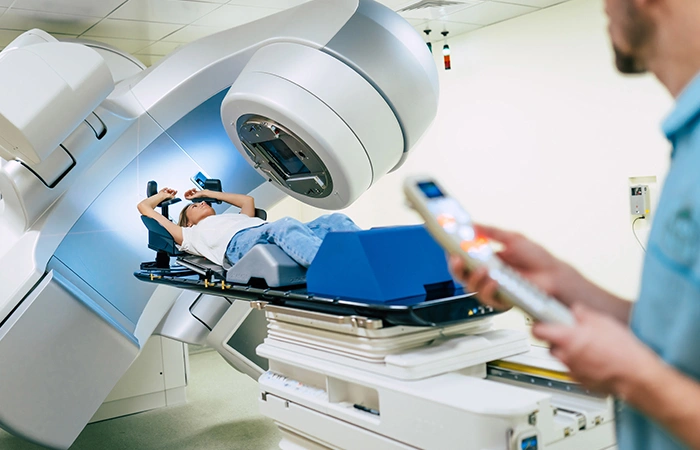
Fig 22
7. Record and verify
The medical physicist is also responsible for importing the plan in a record and verifying software to approve the beams, the total number of monitor units, complete patient management information including the treatment calendar, and the number of fractions per week, this data will be shared into a single user interface, accessible by multidisciplinary teams across multiple locations. Figure 23 shows the MOSAIQ system used to verify all the treatment beams. Figure 24 shows the treatment calendar of a patient to record all the delivered sessions and indicate the next treatment sessions.

Fig 23: beams approval in the MOSAIQ software

Fig 24: Treatment Calendar in MOSAIQ
Conclusion
Radiation medical physicists are responsible for developing, implementing, and monitoring methods that allow patients and those engaged in the treatment process to receive the best radiation treatment possible. Their role starts from the commissioning of the LINAC, analyzing the couch measurements, CT to ED conversion curve, and preparing the staff to proceed with patients’ treatment. The medical physicist’s responsibilities start from importing the CT study sets, creating the plan, evaluating the dose distribution in the organs at risk and the PTV, approving the plan and exporting to a record and verify system to schedule the fractions calendar and finally to record the delivered session to the patient.
References
- https://www-pub.iaea.org
- https://www.aapm.org
- https://www.ncbi.nlm.nih.gov
- https://www.aapm.org
- https://www.cirsinc.com
- https://pubmed.ncbi.nlm.nih.gov
- https://www.usgs.gov
- https://www.cancerresearchuk.org
- Monte-Carlo simulation of the Siemens Artiste linear accelerator flat 6 MV and flattening-filter-free 7 MV beam line https://doi.org
